| Summary | Generates an output image from the specified TikZ commands |
|---|---|
| Tag names | tikz |
| Configuration prefix | tag.tikz |
| Mandatory options |
tag.tikz.path |
| Used options |
tag.tikz.path tag.tikz.img_attr content_processor.tikz.resolution content_processor.tikz.transparent content_processor.tikz.libraries content_processor.tikz.opts content_processor.tikz.template |
| Provided by bundle | built-in |
| API doc | Webgen::Tag::Tikz |
Description
This tag provides support for automatically generating graphics with the fantastic PGF/TikZ library for LaTeX.
Usage
This tag uses the content processor tikz for doing the actual work. To customize the workings of the content processor set the approriate options on the tikz tag itself or globally in the configuration file.
For prerequisites needed to get this working and general usage see the content processor tikz documentation.
When using this tag, you need to set at least the tag.tikz.path option. This path specifies the source path that should be used for generating the image and should therefore not already exist. The destination path is dervied from this path in the usual way. The used path name extension specifies the final image format that is used (a good choice is PNG).
The commands for creating the PGF/TikZ picture are specified in the body of the tag and need to be valid LaTeX code since PGF/TikZ is a LaTeX package. Have a look at some of the examples below to set the power of PGF/TikZ.
Examples
These examples are taken (sometimes a little bit altered) from the great PGF Manual included in the PGF/TikZ distribution.
-
Drawing something simple
{tikz:: house.png} \tikz \draw[thick,rounded corners=8pt] (0,0) -- (0,2) -- (1,3.25) -- (2,2) -- (2,0) -- (0,2) -- (2,2) -- (0,0) -- (2,0); {tikz} -

-
A more complex example with various options set
{tikz:: {path: chain.png, content_processor.tikz.libraries: [arrows,automata,shadows,positioning], content_processor.tikz.opts: "->,>=stealth,shorten >=1pt,auto,node distance=2.8cm, on grid,semithick, every state/.style={fill=red,draw=none,circular drop shadow,text=white}", content_processor.tikz.resolution: 300 72}} \node[initial,state] (A) {$q_a$}; \node[state] (B) [above right=of A] {$q_b$}; \node[state] (D) [below right=of A] {$q_d$}; \node[state] (C) [below right=of B] {$q_c$}; \node[state] (E) [below=of D] {$q_e$}; \path (A) edge node {0,1,L} (B) edge node {1,1,R} (C) (B) edge [loop above] node {1,1,L} (B) edge node {0,1,L} (C) (C) edge node {0,1,L} (D) edge [bend left] node {1,0,R} (E) (D) edge [loop below] node {1,1,R} (D) edge node {0,1,R} (A) (E) edge [bend left] node {1,0,R} (A); {tikz} -

-
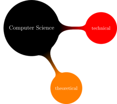
Standard resolution
{tikz:: {path: mindmap.png, content_processor.tikz.libraries: [mindmap]}} \path[mindmap,concept color=black,text=white] node[concept] {Computer Science} [clockwise from=0] child[concept color=red] { node[concept] {technical} } child[concept color=orange] { node[concept] {theoretical} }; {tikz} -
-
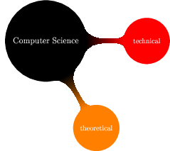
High resolution
{tikz:: {path: mindmap-low.png, content_processor.tikz.libraries: [mindmap], img_attr: {style: 'background:transparent'}, content_processor.tikz.transparent: true, content_processor.tikz.resolution: 300 72}} \path[mindmap,concept color=black,text=white] node[concept] {Computer Science} [clockwise from=0] child[concept color=red] { node[concept] {technical} } child[concept color=orange] { node[concept] {theoretical} }; {tikz} -